Project Overview
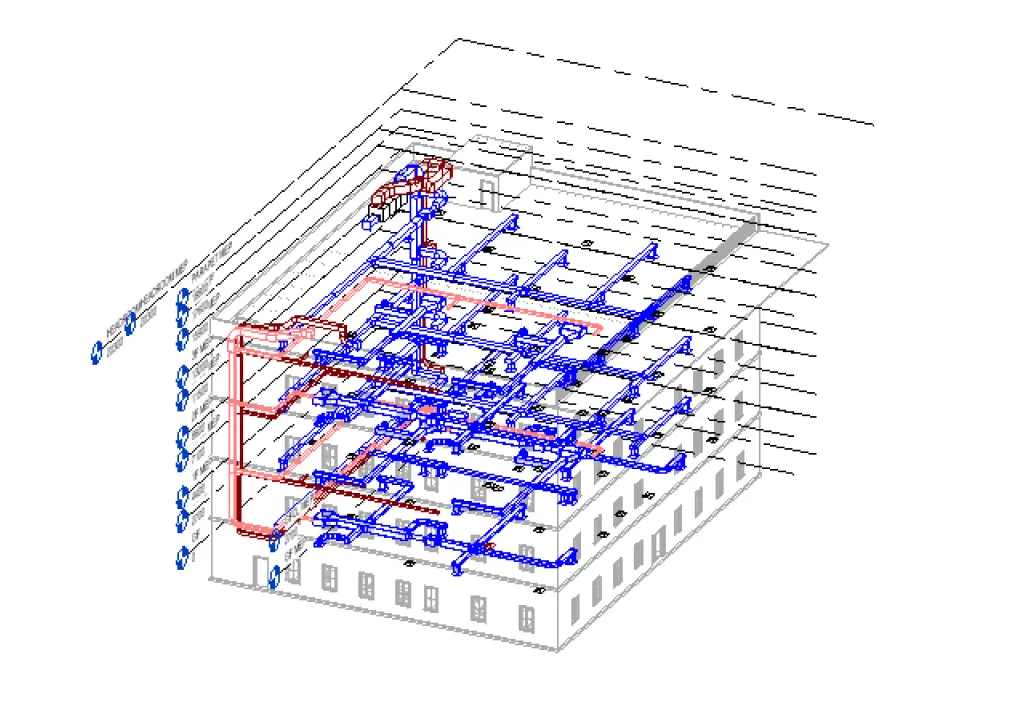
This project involved developing a detailed HVAC Revit model for a G+4+R commercial building based on the client’s design inputs. The scope included accurate duct sizing, diffuser placements, and piping routes without clash coordination. The final model ensured proper system alignment, layout consistency, and readiness for downstream project use.
Client Requirement
The client requested a complete HVAC Revit model based on their design inputs and 2D drawings. Their requirements included:
- Accurate duct sizing and routing
- Correct placement of diffusers, grilles, and terminals
- Proper piping routes for HVAC systems
- AHU and FAHU integration as per design
- A clean model built without clash coordination (as specified)
- 2D drawings generated from the final model
The primary goal was to deliver a precise, well-structured HVAC model that reflected the design intent and assisted with project execution.
Our Approach
We began by reviewing the client’s drawings and specifications to establish system layout, routing logic, and equipment positioning. Using Revit, we modeled all HVAC components including ductwork, piping networks, and mechanical units with accurate sizing and alignment.
The model was developed floor-by-floor to maintain consistency across all levels of the G+4+R building. Even though clash detection was not part of the scope, we ensured logical routing and clean system organization for ease of use. Once the model was finalised, we extracted 2D drawings directly from Revit and prepared them for client review.
The final delivery included a complete HVAC Revit model and coordinated drawing set meeting all project expectations.
Project Outcome
- Delivered a complete HVAC Revit model aligned with the client’s design intent
- Ensured accurate ductwork, piping layouts, and diffuser placements
- Integrated AHU and FAHU units as specified
- Provided clean, professionally 3D model
- Enabled the client to proceed confidently with coordination and execution